International Li-Ion Battery Recycling Summit in China 2023

DrM Shanghai had the opportunity to sponsor and participate at the 2 day congress which took place in Shanghai. With people participating and presenting from the US, China, Europe, India, Japan, Korea and many other parts of the World, it was truly a global event. We would like to take the opportunity to share our experience at this event and express our thanks to the organiser GDMMC who has done a great job to make it happen.

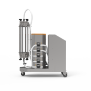
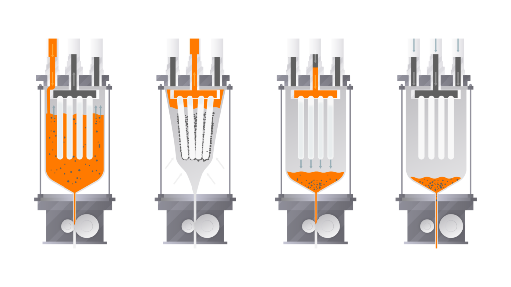
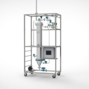
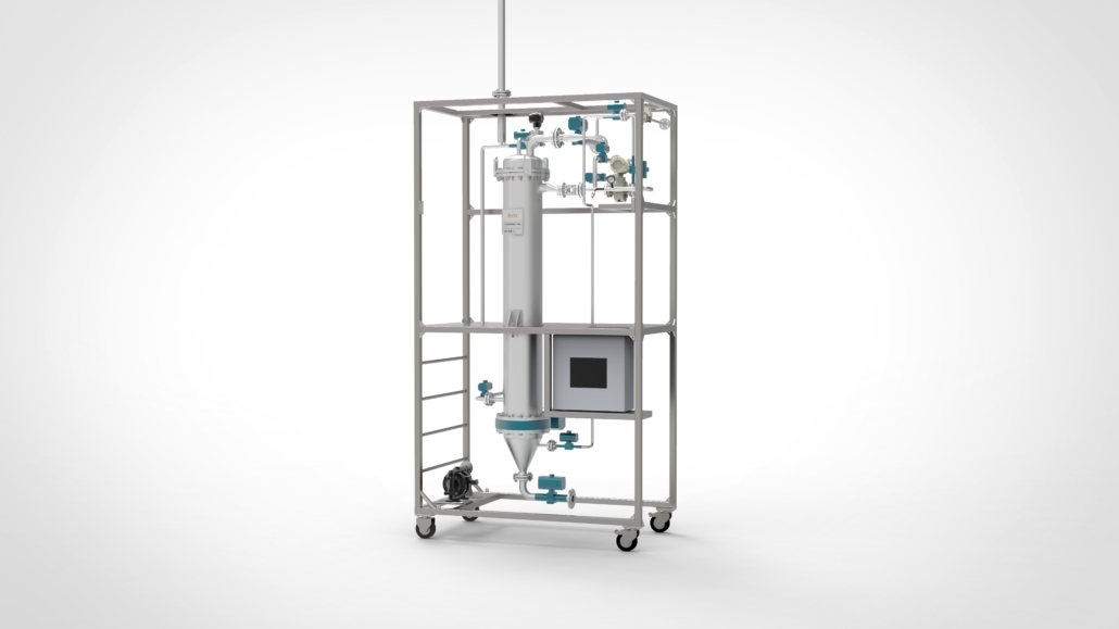
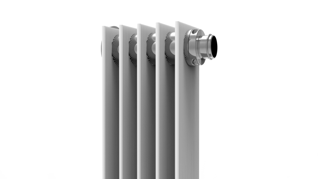
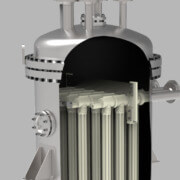
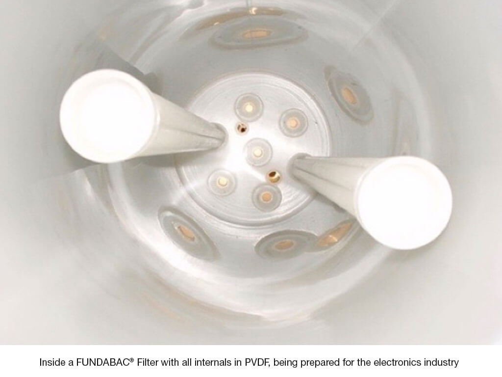
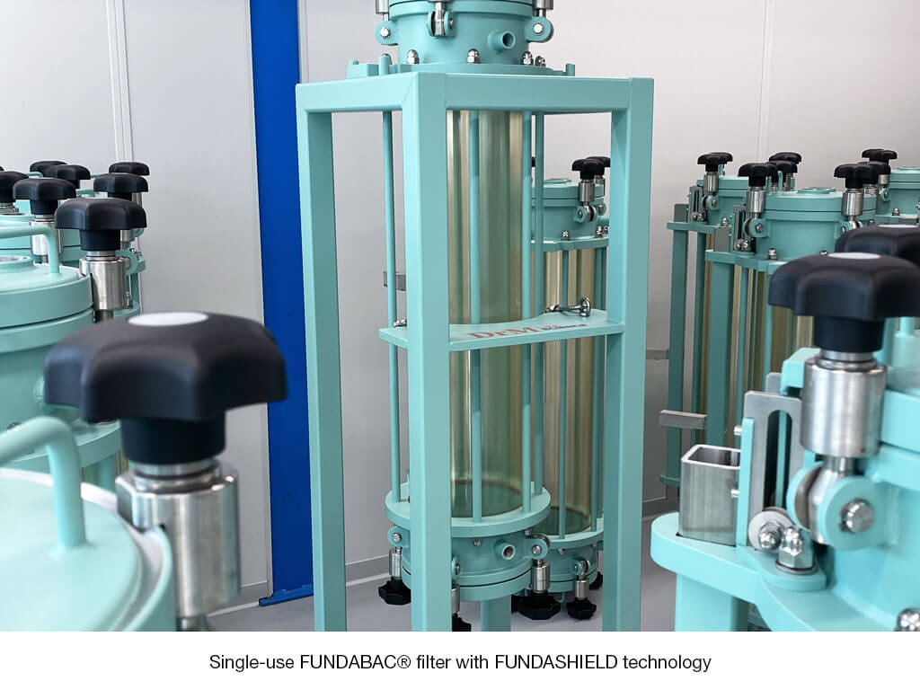
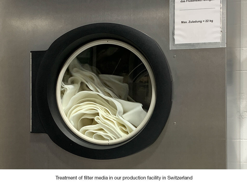
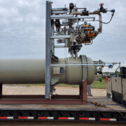
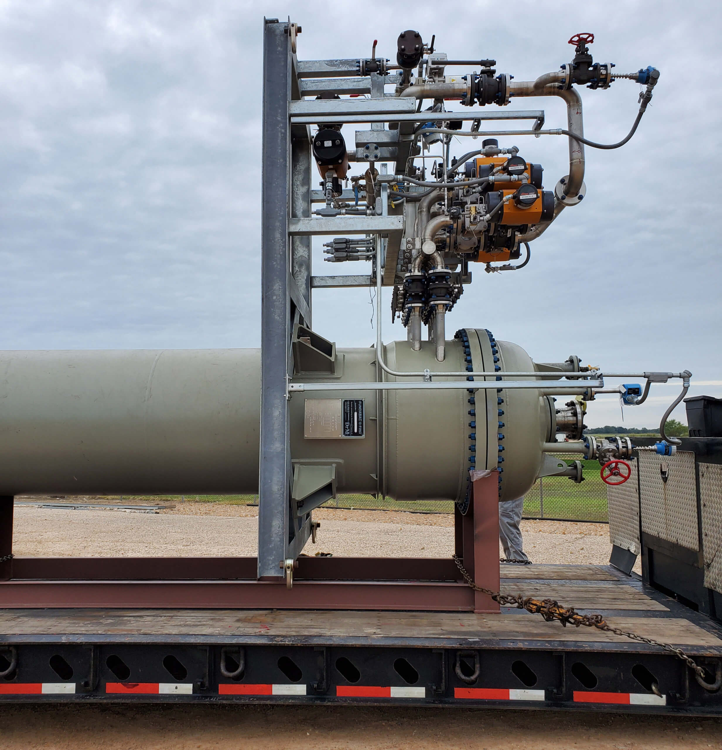
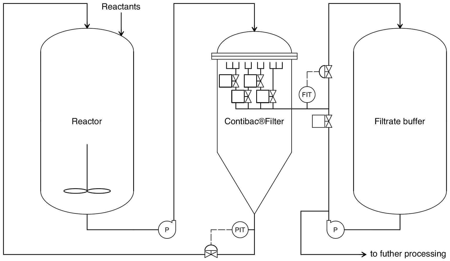
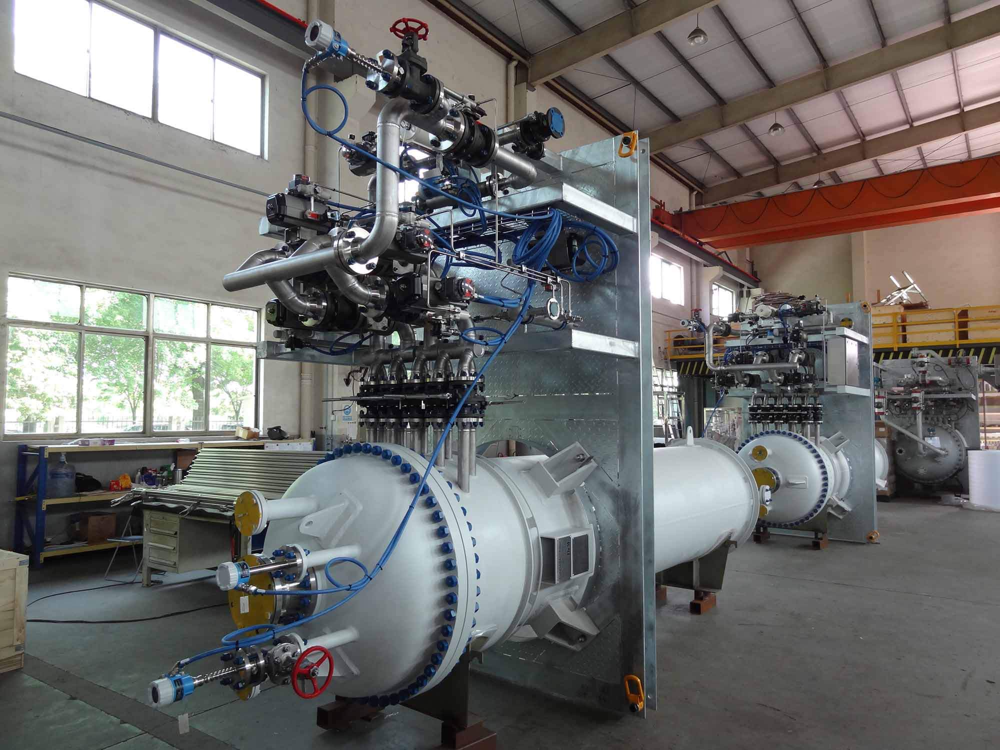
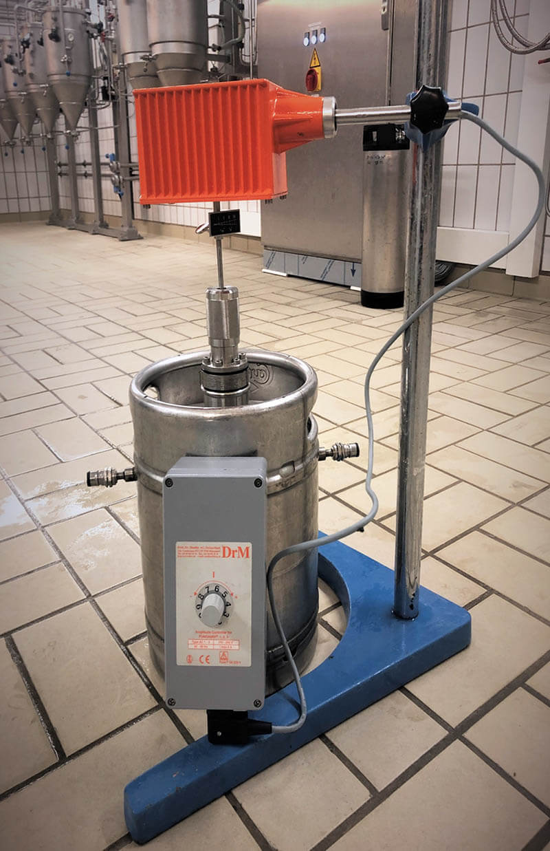
DrM is globally known as a specialist in solid-liquid separation and its FUNDABAC® Filter is widely used in processing of LiB materials. Due to its flexibility, simple construction, closed system and automatic operation it can be adapted to many applications covering purification, product recovery, washing and extraction as well as dewatering of filter cakes.

Actual Market Situation
The battery recycling industry is just starting to take off although there are a number of players who have been in the market for some years. Originally, these companies started out recycling LiB from mobile devices which involves significantly smaller quantities (a few ktpa). In Europe and the US most recyclers crush the batteries (preprocessing) and send the raw black mass (Li, Co, Mn, Ni, Graphite) to Europe or Asia (Korea or China) for further refining. Note that China considers black mass as toxic material which cannot be imported directly. In India it is mainly the lead acid battery recyclers who show interest. China has by far the highest capacities for recycling and this will likely remain so in the future.

Most of the cars sold in China today are already EVs and so the industry stays committed to find appropriate recycling technologies for battery materials. But as there is a significant time lag between the sale of new and EOL batteries (approx. 10 years), there is momentarily a significantly higher recycling capacity on the market than available material. The quantity of EOL batteries is expected to triple or quadruple in the next 7 years while the pre-processing capacity will also increase and flatten off from 2028. Therefore, it is expected that the recycling market will remain in undersupply for the time being. This makes it difficult to be profitable in markets such as the US and Europe. But as recycling quantities increase and economies of scale kick in profits will increase. At the same time it is expected that intercontinental black mass trade will seize and regional markets will become self sufficient.

Due to dramatic developments in material prices there is a continuing shift to battery grades which use less Co and Ni. For example the traditional Li-ion battery (LCO) which we know from our mobile devices contains large quantities of Co and the value of the recoverable materials is nearly three times higher than for LFP (at today’s prices). We can therefore expect a significant reduction of the value of recoverable material in the future. This needs to be accounted for in the investment strategy for LiB recycling plants.

Additionally, an emerging market for replacement battery packs is developing.

Recycling Processes
The industry is divided in preprocessing and refining businesses. During preprocessing the battery grade material is being prepared for refining and mainly involves mechanical steps. In the refining business the raw material is processed to separate and refine the individual constituents.

Preprocessing
Collection: Battery packs, modules, cells, production waste
Discharge: Energy recovery
Dismantling: Recovery of electronics, aluminum, steel, plastics
Crushing and Sorting: Recovery of aluminum, plastics, steel, copper, electrolyte
Black mass: Recovery of Ni, Mn, Co, Li, Graphite, electrolyte

The black mass is collected and sent to a refiner. For example at Hydrovolt (joint venture of Hydromet and Northvolt) it is sent to Hydromet for refining.

Dry vs. Wet Process
Momentarily most refiners in China apply a dry process which basically uses heat to vaporise the electrolyte and lithium and burn off the graphite. These ingredients are not recycled. Korean and some Chinese companies have developed wet recycling routes for which there are various process options to separate the metals from the leached black mass solution:
Electrolytic refining
Solvent extraction
Selective precipitation
Extraction by ion exchange resin

Example of refining process with solvent extraction (Sebitchem, South Korea)
Reduction roasting: Black mass is heated in CO2 atmosphere and the Li2O is reduced to Li2CO3
Water Leaching: The Li2CO3 is dissolved in deionized water at neutral pH
Filtration: The black mass including NMC is filtered. The filtrate contains Li2CO3
RO Filtration: First concentration of Li2CO3 solution
MVR Evaporation: Second concentration of Li2CO3 solution
Washing and drying: Battery grade of Li2CO3
Sulphuric acid leaching: Black mass from step 4 is leached with yields above 95%
Neutralisation: Precipitation of Al and Fe
Solvent extraction: Removal of impurities
Solvent extraction: Extract and enrich Mn
Solvent extraction: Extract and enrich Co
Solvent extraction: Extract and enrich Ni
p-CAM solution tuning: (NMC)SO4

The electrolyte can be recovered by heating the black mass, distilling off the electrolyte and re-condensing it.

GDMMC
Based in Shanghai, China, GDMMC has already held conferences for Li-ion battery reuse since 2012. The next event will be held in South Korea.

Chinese Recyclers US Recyclers European Recyclers Korean Recyclers and projected capacities
GEM Redwood Corvus Energy Sebitchem: p-CAM according to solvent extraction process
CATL Li-Cycle Hydrovolt SungEel Hightech
Huayou Cobalt Northvolt Posco HY Clean Metal: Expansion of p-CAM 155 ktpa (2024)
Brunp Recycling Vianode Cosmo Chemical
Lithium de France JYT
EMAGY KPC (LGC-KEMCO JV): p-CAM 20 ktpa (2024)
Hydromet LG Chem (LGC-HUAYOU JV): p-CAM 100 ktpa (2028)
BASF SK (China GEM JV): p-CAM 50 ktpa (2024)
Umicore CNGR: p-CAM 100 ktpa (2030)
EcoPro (Ecopro-GEM JV): p-CAM 195 ktpa (2026)
Nomenclature
EOL End of life
LiB Lithium Battery
Black mass Powder which is gained from LiB after crushing
Preprocessing First stage of battery treatment where the modules are electrically discharged and crushed
CAM Cathode Material (Ni, Mn, Co)
p-CAM Precursor Cathode Material
AAM Anode Material (Lithium, Graphite, SiO2)
p-AAM Precursor Anode Material
LCO Lithium Cobalt Oxide (LiCoO2) battery. Traditional lithium battery material applied in mobile devices. They tend to have lower capacities than some of the other blends. Li2CO3 is used as precursor for the lithium
NMC Lithium nickel cobalt manganese oxide (LiNiCoMnO2) battery. The blend often contains a ratio of 33% Ni, 33% Mn and 33% Co. It is one of the most successful formulas and is typically used in power tools, e-bikes and other power trains. With a cell voltage of 3.7V and lighter weight than other battery materials it has the highest energy density. Currently at around 300 Wh/kg. Together with LFP this formula is expected to grow the fastest in the coming years.
NCM Lithium nickel manganese cobalt oxide (LiNiCoMnO2) battery. Cobalt is partially replaced by Ni to reduce cost and supply dependency on Co. However, this makes it less energy dense than NMC batteries.
NCA Lithium nickel cobalt aluminum oxide (LiNiCoAlO2) battery. This cathode material has a nominal voltage of 3.6-3.7V and reaches an energy density of 260 Wh/kg. They are often used in EVs and electrical appliances. Panasonic cells of this type are applied by Tesla.
LMO Lithium manganese oxide (LiMn2O4) battery. Cathodes based on manganese-oxide components are earth-abundant, inexpensive, non-toxic, and provide better thermal stability.
LNMO Lithium nickel manganese spinel (LiNi0.5Mn1.5O4) battery. Similar blend as LMO.
LFP Lithium iron phosphate (LiFePO4) battery. Energy density (125-150 Wh/kg) is approx. 40% less than that of NMC batteries. The cell voltage lies at around 3.3V. It does not contain any of the battery materials shared by other Li-ion batteries such as Co, Mn, and Ni and thus is considered significantly more sustainable. Furthermore, it offers high current ratings, superior thermal stability and long cycle life. As of end of 2022 over 30% of EVs in China use this material. It is the material of choice for energy storage.
Electrolyte The electrolyte allows lithium ions to flow between the cathode and the anode, enabling the battery to generate an electrical current through reversible Li+-ion movement. Usually electrolytes for lithium batteries consist of lithium salt dissolved into an organic solvent with the possible addition of organic additives. The common lithium salt-based electrolyte includes lithium hexafluorophosphate (LiPF6) dissolved into a solvent mixture of ethylene carbonate (EC), ethyl methyl carbonate (EMC) and tetrafluoroethyl trifluoroethyl ether (TFE).
PC Propylene carbonate (C4H6O3) solvent used for electrolytes in LiB.
EC Ethylene carbonate (C3H4O3) solvent for electrolytes used in LiB. Compared to PC it has higher chemical stability, higher dielectric constant and better cycle performance 
DMC Dimethyl carbonate (C3H6O3) solvent for electrolytes used in LiB. DMC has strong solubility, improves conductivity and has good low-temperature charge and discharge performance. Due to its low cost it is the most frequently used organic solvent. 
EMC Ethyl methyl carbonate (C4H8O3) solvent for electrolytes used in LiB.

FUNDALOOP: The Efficient and Compact Solution for Downstream Bottlenecks

In recent years, single-use (SU) technology has revolutionized bioproduction efficiency, especially with the introduction of disposable bioreactors in upstream processing. However, downstream processes such as cell harvesting and filtration continue to present bottlenecks in manufacturing.

Currently, typical clarification processes involve primary and secondary clarification steps, such as centrifugation followed by depth filtration, respectively. Although two sets of SU depth filters can be used for primary and secondary clarification, they tend to foul quickly and must be replaced. This increases not only operating expense, but also risk of contamination and plastic waste. To eliminate this bottleneck, DrM is introducing a new FUNDALOOP filtration technology, which combines primary and secondary steps in one unit operation.

The FUNDALOOP technology is the only single-use cyclical cake-filtration system available in the market. A backflush and filter cloth regeneration step is implemented after each cycle, providing a novel way to prevent fouling. When a SU filter clogs, it usually is considered to be spent and must be disposed of and replaced. The cyclical nature of the FUNDALOOP system provides users with all the benefits of disposable technology, such as contamination reduction and ease-of-use, while also prolonging the lifespan of one filter cloth for multiple cycles. Operating in cycles also provides space saving benefits, as one 30L filter bag can process 2000L+ of material, depending of culture density.

The filter technology is based on the addition of diatomaceous earth, which combines with cells and other process solids to form a porous cake. This cake is what actually performs the filtration while the filter cloth itself simply acts as a support for it. Unlike in a depth filter, the filter medium thus can be coarse and thin so as to not trap debris over time. The four main steps of a FUNDALOOP filtration cycle are shown in Figure 1. Four filtration elements covered by a filter cloth are surrounded by a multi-layer polyethylene film, creating a single-use multicycle sterilizable 30-L bag. The bag is connected to corresponding inlets, a filtrate outlet, and discharge hoses and is sealed airtight relative to the transparent vessel housing it.

Figure 1: The four main steps of a FUNDALOOP filtration cycle.

In the first step, cell culture fluid is pumped into the bag and filtered, creating a porous cake of solids on the elements. Once filtration has ended, heel-volume filtration is executed by introducing pressurized gas to the area in between the housing vessel and the plastic bag. That squeezes the remaining liquid through the filter elements and out through the filtrate line. Cake washing is an optional step to ensure that product remaining in the cake can be recovered. At this point, the filter cloth is regenerated by pumping a sterile liquid such as wash buffer, water for injection (WFI), or filtrate back in the opposite direction through the filter elements to dislodge the cake and other fine particles that may have become embedded in the cloth. Finally, the discharge valve opens so that remaining liquids and solids are discharged from the bag. This cycle can repeat up to 100 times.

Experimental results obtained at laboratory scale using a 200-mL Nutsche filter operated at a constant pressure of 1.5 bar showed that with cyclical function and cloth regeneration, a FundaLoop filter can maintain high flow rates.

Possible applications of the FundaLoop filtration system include the bioprocessing industry, where it can be used for clarification of recombinant proteins from CHO culture or separation of adherent cell lines from microcarrier beads. It may also be used for clarifying microbial culture, depending on cell density.

In conclusion, the FundaLoop filtration system has shown significant advantages over depth filtration in terms of flow rates, laboratory footprint, and filtration area. Compared to existing SU filtration techniques, our technology stands out due to its cyclical function and cloth regeneration, which can minimize fouling over time and improve overall efficiency and capacity. Additionally, the ability to combine primary and secondary clarification in one unit operation eliminates the downstream bottleneck, reducing the need for multiple filters and the associated costs.

CONTIBAC® RX filter pilot unit

CMMF – Combined Micropollutant and Microplastic Filtration as innovative quaternary municipal wastewater treatment

PAK precoat candle filtration

Emerging contaminants in the environment are an ongoing national and global water challenge. Two groups of contaminants are of higher concern in waste and drinking water management: micropollutants (MP) and microplastics (MPlas).

Municipal wastewater treatment plants are considered as point sources. Different countries already regulate their discharge pathways via wastewater treatment plants with, for example, a target value of 80% reduction.

In the CMMF project, we have developed a technology that successfully removes microplastics and micropollutants, and contributes to sustainable ecology through its high effluent quality. The technology is based on the DrM precoat filtration, in which a vertical installed textile (filter cloth) is precoated with different functional layers (filter cake).

CONTIBAC® RX filter pilot unit

CONTIBAC® RX pilot unit.

A pilot plant with 1m2 filter cloth area was installed on a municipal wastewater treatment plant (WWTP Rancate, 50’000 PE), treating secondary clarifier effluent to validate the laboratory findings and operate the system under real conditions.

The micropollutant elimination performance was correlated with absorbance measurements at 254 nm (Spectral absorption coefficient – SAK) and regular HPLC-MS/MS analytics. The targeted 80% removal efficiency was reached with 2 and 4 kg/m2 powdered activated carbon precoat.

Pilot plant absorbance reduction chart

Pilot plant SAK reduction over a filter runtime of 24h.

Quantitative reduction chart

Quantitative reduction of fifteen analyzed micropollutants from a 24h composite sample.

The precoat candle filter can operate directly and does not require any upstream reaction or sedimentation tanks. After an operating time of up to 24 h the filter is exhausted and needs to be backwashed and recoated. The partially loaded carbon cake can be used again for a second precoat. This shall be done to reduce the activated carbon consumption.

Today, the carbon consumption amounts to approx. 2.8 – 3.2 mgPAC/mgDOC treated wastewater.

Once operated with a carbon cake, the total suspended solid (TSS) retention of the filter is guaranteeing low values of < 1 mg/L TSS. Hence, the PAK-retention can be assumed higher than 99%.

Close-up of the CONTIBAC® RX filter media.


Close-up of the CONTIBAC® RX filter media.

Microplastics retention down to 50 µm particles is investigated in the project. The total solid retention indicates a complete retention is reached for particles bigger 100 µm. The characterization of the treatment plant effluent and pilot plant effluent is ongoing.


Conclusion

  • The CMMF project idea of operating a PAK precoated candle filter as quaternary treatment step is feasible and demonstrated treating secondary clarifier effluent of the wastewater treatment plant of the WWTP Rancate (TI). Compared to today’s state-of-the-art applications, the new process convinces with:MP reduction to comply with water directives
  • Effective solid particle retention (TSS concentration of < 1 mg/L in the effluent)
  • Direct precoat filtration, no upstream reaction Tank required
  • No or negligible activated carbon loss
  • Carbon recoating ensures good PAC utilization
  • Increased COD retention
  • Modular setup allows for high process flexibility
  • Low space requirements
  • Fast start-up
  • Resistant to solid load and flow fluctuations
  • Process can be fully automatized

These pilot tests and the evaluation of the results, were carried out from November 2021 – December 2022, by:

Scuola universitaria professionale della Svizzera italiana, CH-6850 Mendrisio, Dipartimento ambiente costruzioni e design, Istituto Microbiologia – BET.

Project Partners

Dolder AG, CSD Ingenieure, SUPSI, CDAM and DrM, Dr. Mueller AG.

Meet us at Achema 2022

We are taking part in Achema, the world’s leading trade show for the process industry set for August 22-26.

Meet our team at Hall 12 / Booth 52 for an in-depth presentation on our solid-liquid separation, vibratory mixing and single-use solutions.

For more information about Achema go to www.achema.de/en/

Click the button below to request a free complementary entry ticket.

DrM is expanding

Our DrM subsidiary in Poland is getting bigger! The perfect place to expand our operations in Włocławek has been found. We had the opportunity to take over a company located around 10 minutes by car from the city center. It is a prime industrial location, perfectly suited for our operations.

This new spot covers 24000m2, an immense space to expand future operations even further. It is 4x bigger than the last place we operated on and serves as the perfect base for a future with immense growth ahead.

FUNDABAC® for Semiconductors

Since the onset of the industrial revolution the chemical industry spread itself into more and more applications targeting the industrial and consumer markets alike.

Especially organic chemistry gave a never ending playing field, starting with simple products, such as fatty acids, dyes and pigments but developing into complex polymers and active pharmaceutical ingredients making our lives more comfortable and healthier. Biochemistry opened another door of seemingly endless possibilities.


The rise of the electronics industry

On a separate path, with the invention of  semiconductors and the commercialization of electronics into the consumer goods and IT market, the electronics industry has reached massive scale. Accordingly, speciality materials and complex chemicals are applied alongside value added production chains such as wafer processing, chip production, display technologies, optoelectronics, PCB materials, light emitting components, high strength casings, flexible displays, temperature and acid resistant polymers, battery compounds such as Lithium, Cobalt, Nickel, Manganese, Graphite, rare earth elements and many more.

Additionally, miniaturization into nanoscale has lead to increasingly complex production and assembly processes requiring larger equipment and automation to achieve the required precision. Impurity levels in precursors and workspace play an instrumental role for reaching high yields and long life time. Clean rooms which used to be a domain of the biotech industry have become an inevitable part of this industry.


Our role in the electronics production market

Over the years the FUNDABAC® Filter has found its role in this market with countless applications for various products and processes such as silicon shaping, purification of photoresist precursors, metal oxide precursors for CMOS semiconductors, ultra thin copper foil production, sapphire shaping, high purity alumina, LCD glass etching, optoelectronics and various waste water treatments.

Due to its design flexibility and adaptability in terms of materials of construction the filter finds its use in high and low solids feed applications, wide temperature ranges, particle sizes down to sub micron levels as well as for a large range of solvents, acids and caustic solutions.

DrM has extensive experience with high performance plastics to be used for filter elements, support manifolds, fittings and couplings and can build equipment where no metals are in contact with the processing fluids. This prevents any leakage of metal ions into the process. The extensive range of filter media creates an enormous flexibility to adapt to various process conditions.

For small batches our FUNDASHIELD product line offers a completely novel approach to single use equipment. The filter elements are enclosed in a sealed bag to protect environment and operator from harmful substances. And unlike standard cartridge filters, they can be back-flushed multiple times while keeping the solids enclosed in the filter bag. This extends the life time of the filter.

Single-use FUNDABAC® Filter with FUNDASHIELD technology

Due to a special pressure housing the bag can be pressurized from the outside by air to squeeze any remaining liquid from the solids and produce a compact cake. Finally, the bag containing the cake is sealed and removed.


Our dedication to purity

Recently, DrM has invested heavily into new fabrication facilities to be able to meet the stringent standards requiring low impurity levels in our equipment and specifically consumables such as filter media. Traceability of our products on a production lot level back to our suppliers assures transparency across our value chain.

Production, preparation and packaging of filter media is centralized in Switzerland from where they are shipped all over the globe. However, local warehouses in various continents allow for quick reaction to clients’ needs. This is a fast moving industry with the need of agile and competent partners.

We at DrM feel well placed to fulfill these requirements. With distributed lab facilities and pilot units together with a team of process and service engineers we can react within hours to prevent bottlenecks and keep the project on a fast track. Our vast database of test reports allows us to estimate filter sizes for unknown product mixes, which can give a more accurate picture on a limited time budget during the planning phase.

Need help with a project? Contact one of our dedicated engineers.

CONTIBAC® Filter for continuous catalyst recovery

Slurry bed reactions and application of CONTIBAC® Filters for continuous catalyst recovery

CONTIBAC® Filter for continuous catalyst recovery

Summary

  • Slurry bed catalyst reactors are popular equipment despite their more complex operation. 
  • Catalyst hold up plays a major role for optimisation of the process. 
  • In continuous reactor systems continuously operating separation equipment are required. 
  • The CONTIBAC® offers a good option compared to a number of other continuously operating separation equipment. 
  • Two case studies exemplify its functionality.

Fixed vs. Slurry Bed Reactors

The chemical industry is heavily relying on heterogeneous catalysis for the synthesis of the thousands of compounds required in today’s complex world. For continuous operation fixed bed catalysts are often preferred from an operational point of view. The reactor needs to be filled once and the catalyst can stay in operation for an indefinite period of time. The feed product can pass through the reactor bed and the final product is synthesised and collected for further purification. No cumbersome separation of the catalyst is required. 

Unfortunately, we seldom have such ideal conditions and the process engineers need to carefully weigh investment and operating cost as well as product yields with slurry bed reactors. A slurry catalyst is more complex to handle as it is fed into the reactor as a powder and needs to be removed from the product stream for recycle. However, it offers a number of benefits compared to a fixed bed reactor. 

  • Typically, it is shown that due to improved mixing in a slurry bed reactor, heat transfer is more efficient and therefore cooling surfaces can be reduced. This could also mean, that the reactor can run at higher throughput. To partially compensate this issue and increase the heat transfer in fixed bed reactors, they are often run at a high recycling ratio, which however increases pumping capacity and pressure drop across the bed. Due to increased erosion of the catalyst at these high flow rates, separation and purification cost rises. 
  • Fixed bed reactors can run into plugging issues as by-products, such as long chained hydrocarbons, can accumulate within the structure of the bed, hence gradually reducing yield over its life time. 
  • Often it is not possible to pass the reaction product from the fixed bed reactor straight to the downstream purification steps such as distillation because catalyst fines would block the distillation column over time and create all sorts of process upsets. Hence, some sort of solid/liquid separation equipment is required.
  • As catalyst efficiency decreases during its operating time, increasing the reaction temperature gradually can partially offset this loss in a fixed bed reactor. However, eventually, the catalyst needs to be replaced and this requires a shut-down of the plant. In a slurry bed reactor, the catalyst activity can be maintained by constantly adding fresh while purging parts of the used catalyst. 

Flexibility and efficiency of slurry bed reactor accounts for its popularity

From above analysis it can be understood why slurry bed reactors have such widespread use. Especially in fine chemicals where process conditions need to be tuned regularly, a slurry bed catalyst offers more degrees of freedom. However, to guarantee stable reaction conditions the catalyst concentration should remain constant over time. Additionally, catalyst hold-up in the separation equipment should be reduced to the minimum. This requires a constant recycle of catalyst from the product feed. Therefore, a continuously operating separation equipment is of benefit.

Requirements for separation equipment in continuous processes

In contrast to a batch operation where the separation equipment can recycle or purge the catalyst during the down time, in a continuous production no down time period is permitted. Depending on the type of catalyst, process conditions and ease of operation a few types of equipment are applied. Decanter centrifuges and cross-flow filters are typical examples. 

While decanter centrifuges can operate reliably with fluctuating feed conditions they are often not able to produce the required product quality as catalyst fines remain in the product stream. Also, abrasion of the catalyst as well as the high speed rotating parts leads to maintenance and down time while increasing concentration of fines in the product stream. Finally, when full containment is required, gas tight design must be applied to decanter centrifuges, which further increases the complexity and the cost of the system.

Pros and Cons of traditional Cross-flow filters for catalyst recovery

Cross-flow filters come in many forms. For catalyst separation which is often done at elevated temperatures, rigid membranes, preferably made of sintered stainless steel or ceramics are applied. While these filters offer excellent product quality their main down side is plugging of the fine filtration surface over time. Due to their rigidity there is hardly any means to clean them in situ. Regenerating those elements is a complicated endeavour which requires complete disassembly and off-site treatment under high temperature for pyrolysis of the entrapped scale. Cross-flow filters normally operate at high tangential velocities, typically between 3 and 5 m/s. The high shear rates which are developed at those speeds reduce the laminar flow layer at close range of the membrane surface and therefore prevent solids accumulation which would reduce permeate flow, eventually leading to fouling. However, such shear rates also put additional strain on the catalyst particles creating abrasion and forming fines. These fines reduce filtrability and require tighter membrane porosity, which again enhances fouling. Finally, these high tangential velocities come with a pressure loss between the feed inlet and the retentate outlet. Hence, the transmembrane pressure (TMP) is higher at the inlet than at the retentate outlet, which results in non-uniform filtration characteristics across the length of the module with higher fouling tendency.

Cross-flow filtration vs. CONTIBAC® Filter

The CONTIBAC® is a viable alternative for continuous catalyst recovery

As an alternative to the above, a continuously operating CONTIBAC® can offer a number of advantages. Its basic filter operation resembles a cross-flow filter system, with the main feed entering at the top and the retentate exiting at the bottom, the gravitational force is effectively used in addition to the downwards flow to continuously remove the catalyst from the filtering membrane.

CONTIBAC® filters apply a flexible filter media which is much more resilient to any kind of blocking when compared to rigid elements. As a result the filter can operate at significantly lower differential pressures. In a CONTIBAC® filter the TMP is constant and always lower. Lower pressure drops reduce compaction of the solids adjacent to the filtering membrane which enhances removal of the catalyst particles. Additionally, the cross flow velocity can be lowered, reducing abrasion of particles. The overall particle size distribution is maintained over a longer period of time which increases the life time of the catalyst. 

Normally, filter membranes with pore sizes matching the particle size distribution of the catalyst are applied. This enhances the risk of having catalyst fines in the filtrate during the initial phase of usually 10-15 seconds. However, this can easily be recycled. 

From the operational side, smaller pumps and pipe sizes can be applied. If or when required, individually controlled filtrate groups within the same filter vessel allow independent regeneration at certain intervals while the rest of the groups remain in operation, ensuring constant flow. The well-proven concave-convex form of the filter element effectively releases solid scale and prevents fouling.

Should the filtering media eventually fail, they are easily replaced at significantly lower cost when compared to sintered metal or ceramic elements.

Needless to say, these high performance systems run fully automatically and have a proven track record for many applications across the processing industry.

CONTIBAC® Filter

Typical process flowsheet for a continuously operating CONTIBAC®

Case studies

Case 1:

The company was originally running a continuous hydrogenation process with sintered metal filters applied for the continuous recycling of the Pd catalyst into the reactor. However, due to frequent fouling of the elements the process was essentially discontinuous as the filter needed to be opened manually and cleaned. 

They decided to rent a 4.5 m2 continuously operating CONTIBAC® pilot unit to understand the feasibility of such a solution. They initially encountered two issues: 

  • As the filter was connected straight to the reactor, some H2 gas was carried over to the filter which accumulated in the top. As this gas cushion grew with time, filtration was disturbed and the flow rate reduced. With a simple purge loop we could eliminate this issue. 
  • Some tar forming in the reactor also led to partial fouling of the membrane. We then implemented an additional liquid flushing step which quickly recovered the lost filtrability. 

In the meantime, the client has a number of filters in operation and is happily recommending this technology.

Case 2:

For a green field project, the company was looking for a continuously operating catalyst filter solution which promises less fouling than what they were used to. A continuous CONTIBAC® was finally chosen. The original design was such that by applying a low TMP and high enough cross flow speed no further means for solid removal are required.  However, for safety reasons a flush back system was implemented which allowed uninterrupted filtration. After commissioning and startup it was noted that after a 12h filtration period the TMP started climbing. Hence, the back-flush was put into use, which could completely recover the flow. In the meantime, the second system has been delivered in another green-field site.

CONTIBAC® Filters for continuous catalyst recovery

Two filter packages for continuous catalyst filtration in a production of a plastics intermediate before delivery to a chemical multinational

Clear recycling pellets

Purification challenges and their state-of-the-art solutions in plastics recycling

The challenges of current recycling processes

As environmental awareness from people, companies and governments has increased over the last few decades, noticeable efforts are being made in order to bring recycling processes of plastics or synthetic textiles to commercial scale.

A number of recycling technologies are under investigation, each with certain complexities and peculiar performances, but the ultimate goal of all of these is to economically manufacture cloths or other objects from recycled polymers rather than from virgin oil feedstock.

Purely mechanical processes, involving crushing/shredding of end-of-life objects before melting them into granules represent an older approach and are not capable o

f removing impurities chemically bound in the original structure of the recycled object; a typical example is constituted by pigments, dyes or other substances used to colour or to otherwise modify the properties of the original object. Plastics recycled this way have therefore restricted use, limited to products of inferior quality.

Plastic Pellets with impurities

Achieving plastics of a cleaner grade

In order to achieve plastics of a cleaner grade, comparable to what is produced by petrochemical processes and therefore with an identically wide range of application, recycling operations must include a purification step. These newer processes are more technology-intensive as they typically involve the depolymerisation of the plastic into the constituting monomers or its dissolution into specific solvents. When dissolution methods are applied, the molten plastic and the solvent are found as a single, homogeneous liquid phase and the molecular structure of the polymer (e.g. PP, PET) is kept. Impurities remain in suspension and can be removed by means of solid-liquid separation techniques.

A fundamental issue is represented by the fact that the above mentioned dissolution processes are typically carried out under harsh conditions: high temperatures, high pressure, chemically aggressive or otherwise hazardous solvents can be present, even in combination. As a result, the selection of the equipment to be used for the solid-liquid separation is significantly restricted to very few technologies only.

The ideal equipment is fully enclosed, thus preventing the process media from getting in contact with the external environment, working automatically, so not requiring intervention by operators, and is of course fabricated with materials capable to withstand the process conditions. Also, the separation efficiency shall be good enough to allow the removal of particles being typically in the size range of few units of a µm, down to fractions of a µm. This is for instance the case of titanium dioxide, one among the most common pigments used in the textile industry.

DrM, Dr. Mueller AG is a Swiss-based Company supplying sophisticated solid-liquid separation systems since 1982. DrM proprietary technology is installed in several thousands of plants worldwide and features candle type filter elements equipped with filter cloths and installed into a pressure vessel. The maximum operating pressure of the system is defined by the vessel design only, thus is virtually unlimited. Also, thanks to the absence of moving parts, the selection of materials of construction for both the vessel and the internal parts is not subject to any specific restriction imposed by temperature, pH or chemical compatibility whatsoever.

The inherent flexibility of the filter cloth and the peculiar design of the DrM candle element allow a thorough regeneration during the back-washing step and prevent the progressive blinding typically experienced with rigid elements, even when back-washed.

Filter cloths are normally fabrics themselves, and their thermal resistance sets the limit of applicability for the system as a whole. Since a few years DrM can offer filter cloths made with stainless steel filaments. This unique feature combines the flexibility of a fabric with an outstanding resistance up to 300°C continuous operating temperature.

beer brewing

The FUNDAMIX® used for dry-hop in the beer brewing process

beer brewing

Testing three different dry-hopping systems on beer quality

The Weihenstephan experimental brewery, a branch of the Technical University of Munich, has examined the influence of three different dry-hopping systems on beer quality as part of a diploma thesis at the Department of Brewing and Beverage Technology.

A static, a dynamic reference system and the FUNDAMIX® were compared. The tests were carried out with filtered and unfiltered Weihenstephaner Original Hell from the Bavarian State Brewery Weihenstephan using two different hop pellet types (type 45 and type 90).

It has been a well-known fact since the early Middle Ages that hops contribute to the shelf life of beer.

In the modern brewing industry, however, the focus is not only on the shelf life of the beer, but also on the introduction of hop-typical aromas which give the beer a special taste. Due to the steady growth of the craft beer scene and the brewing of beers with increased hop content, the industry had to find efficient solutions to transfer the hop aroma into the beer.

Today there are essentially two possibilities of dry-hopping (hop-stuffing) in the brewing industry, either by adding into the tank (static system) or through a dynamic system (pumping over).

Extracting valuable aroma through dry-hopping

In the diploma thesis three dry-hopping systems were examined: the static system, the dynamic reference system of the research brewery of the Technical University of Munich and the FUNDAMIX®.

The idea of dry-hopping is to extract the valuable aroma substances from the hops and to transfer them with minimal losses into the finished beer.

The actual dry-hopping is carried out in the cold area (storage) of the brewery, the classic hop addition in the hot area of ​​the brewery.

Studies have been able to prove up to 500 different essential oils or hop oils, but only 21-25 of these essential oils can be directly associated with the beer aroma. In terms of oil factors, these aroma substances are perceived as resinous-herbal, flowery, citrus-like or pleasantly hoppy.

The contact time of the hops has a major influence on the concentration of the hop aromas and the change in pH during dry hopping. The pH value plays an important role in the shelf life of beer.

Testing beer quality using a FUNDAMIX®

Figure 1 shows the complete test setup of the FUNDAMIX®. The resulting amplitude was approximately 1-2 mm. The test volume of 5 l resulted in a hop dosage of 4.7 g (type 45) and 9.4 g (type 90).

The weighed hop pellets were placed in a cloth bag (mesh size 300 μm). In the first step of each cold hops test the 5 l drum was steamed in order to sterilize it. Then the barrel was screwed on and the previously weighed hops were placed in front of it and rinsed twice with CO2 and pre-tensioned to 1 bar. The now pressurized drum was filled with 5 l filtrate or prefiltrate and connected to the FUNDAMIX®. After 10 minutes the dry-hopped beer, without hop bags, was transferred into a pre-stressed 20 l Cornelius keg and spiked to 0.9 bar. The beer was stored for 14 days at 1°C and then filled into 0.33 l bottles using a counter-pressure filler. The bottles were then used for further analysis. In addition to the main experiments, the effect of the vibration time on the extraction of the hop aroma substances and bitter substances was investigated with the FUNDAMIX®. The contact times were 10, 20, 30, 40, 50, 60 and 90 minutes.

The focus of the study was on beer quality, therefore the leading components of the hop aroma, the chemical-physical cloudiness and the foam stability were examined. In addition, a sensory tasting of the beers was carried out according to the beer tasting scheme of the German Agricultural Society (DLG).

The tasting was carried out independently by four trained individuals.

It was found that the highest percentage increase (approx. 40%) in the leading components (humules and mycoses) of the hop aroma occurs with a contact time of 40 minutes. In the case of the FUNDAMIX® an optimum time of 20 and 40 minutes was found.

Dry-hop with the FUNDAMIX® has no influence on foam durability.

At the tasting, the FUNDAMIX® samples (see Figure 2) were generally perceived as very pleasant. The filtered beers were given preference in the ranking.

All samples from the vibration plate and the static test were generally perceived as rather disharmonious.

While the intensity and quality of the hop aromas of the FUNDAMIX® samples were assessed as lower, the FUNDAMIX® system clearly stood out in terms of the harmony overall. In conclusion we can say that cold hop with the FUNDAMIX® system was generally rated as much more pleasant and tasty than the other two dry-hop systems.

Beers with harmonious taste are favored by the market.

Figure 2: Tasting overall comparison: The summary of the tasting and the scores of the DLG scheme.

Overall a more harmonious tasting beer and a faster dry-hop process with the FUNDAMIX®

It was shown that the system used had an influence on the quality of the beer, but here a distinction must be made between sensory tasting and analytical evaluation. The FUNDAMIX® beer, for example, which was tamped for a very short contact time of 10 minutes, performed better in the tasting than the other two systems, where the contact time was up to 48 hours.

The tests have shown the potential of the FUNDAMIX® in terms of significant time savings in the dry-hop process. However, further studies on a larger scale are necessary.

Particle size analyses are still to be carried out as part of an internship to determine the influence of the different currents.

The next step is to run the tests in the experimental brewery in the 10hl plant, where a 1000 l container for dry-hop is available. There, energy costs could then be recorded under standard market process conditions. Furthermore, a comparison with an existing established product can be made with regard to the influence of shear force and oxygen absorption during pumping and cleaning of the system.

Washing hands

Water, sanitation and hygiene – one of the best defences against COVID-19

Just a few months ago the World was still normal, at least what we consider our World. Now, we have been blasted into a new normal with an unknown outcome. Lives are shaken up, markets collapsed and companies are struggling to find their place. But with every change there are opportunities. While searching to find our place within the mega trends centred around homeland, health and environment, in the midst of this crisis we at DrM are observing increased activities in a number of markets which we have been serving in the past. These new circumstances are now redefining our short term businesses to a certain extent which leaves us with new possibilities.

The increased worldwide demand for masks has created investments within the supply chain of many raw materials around this mass product. A prominent material is viscose. While early viscose production plants did not focus on quality, newer facilities  see opportunities in better grade products. The FUNDABAC® Filter is a workhorse in this tough industry where exposure to high temperatures and aggressive chemicals complicates the life of equipment. Most masks are nowadays fabricated in Asia and hence our market for this application is in this region. Delivery time is a main driver and with our local production capacities in Asia we can leverage on this fact.

The need for cleanliness is another driver for increased supply of various sanitisation and disinfection products all around the World. Higher standards in drinking water supplies demands new capacities in chlorination products. In Europe where past plants used older mercury technologies to produce chlorine, there was a rush in investments into membrane electrolysis as new legislation was put into force. However, difficulties in transporting this dangerous good created further opportunities for smaller facilities to supply local markets centred around the drinking water industry. With both our FUNDABAC® and CONTIBAC® we are proud to have a predominant position in this industry. Our robust technology is responsible for a large part of the supply of this disinfectant with hundreds of our filters spread all around the globe.

However, sanitisation products based on alcohol and detergents have seen the highest growth. Surfactants play an important role in these product categories. Due to the need to increase capacity on a short term notice we decided to offer our large fleet of pilot units for this purpose. They are used to de-bottleneck production facilities for products such as surfactant additives and deodorisation of ethanol enabling our clients to satisfy local market demand.